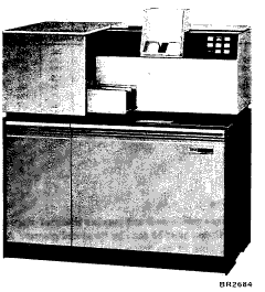
Figure 38. IBM 1442 Card Read Punch
Eighty-column punched card input and output is provided to the 1130 system by the IBM 1442 Card Read Punch, Model 5, 6, or 7, and/or the IBM 2501 Card Reader.
The IBM 1442 Card Read Punch (Figure 38), Model 6 or Model 7, provides both card input and card output for the 1130. The 1442 Model 5 is a card punch only and is considered the companion unit to the 2501 to provide a separate card path for card input and output. However, a model 6 or 7 may be installed with the 2501 in place of a model 5; in this case the 2501 should be considered the primary input unit. Functionally, the 1442 model 5 has the same punching characteristics as the 1442 model 7.
The 1442 is a single unit that processes cards serially, column by column, from a single supply hopper. All cards first pass the read station (model 6 and 7), then the punch station. This permits each card to be read, punched, or read and punched. Reading and punching cannot occur simultaneously -- that is, one card cannot be punched while the following card is being read -- because the reading and punching rates are different.
Maximum machine speeds are:
| Card Reading | ||
| Model | Cards per minute | |
| 6 | 300 | |
| 7 | 400 | |
| Card Punching | ||
| Model | Columns per second | |
| 5 | 160 | |
| 6 | 80 | |
| 7 | 160 | |
Maximum reading rates are attained only when successive start read commands arrive early enough to re-energize the read clutch before the clutch latch point is reached. To accomplish this, successive start read commands must arrive within 35 milliseconds, model 6 (or 25 milliseconds, model 7) after the operation-complete interrupt is given by the card read punch. If a start read command does not arrive within this time, the maximum reading rate becomes 285 cards per minute for model 6 and 375 cards per minute for model 7.

Figure 38. IBM 1442 Card Read Punch
Punching rates depend on the position of the card when the last column has been spaced or punched. The punching speed ranges are:
The approximate time required to process a single card is:
The following table shows the approximate punch cycle times and cards-per-minute rates based upon the last column punched.
| Last Column Punched |
Punch Time (ms) | Total Punch Cycle Time (ms) |
Cards per Minute | |||
| Model 6 | Model 5&7 | Model 6 | Model 5&7 | Model 6 | Model 5&7 | |
| 1 | 13 | 6 | 229 | 169 | 262 | 355 |
| 10 | 125 | 63 | 341 | 226 | 176 | 265 |
| 20 | 250 | 125 | 466 | 288 | 127 | 208 |
| 30 | 375 | 188 | 591 | 351 | 102 | 171 |
| 40 | 500 | 250 | 716 | 413 | 84 | 145 |
| 50 | 625 | 313 | 841 | 476 | 71 | 126 |
| 60 | 750 | 375 | 966 | 538 | 62 | 112 |
| 70 | 875 | 438 | 1091 | 601 | 55 | 100 |
| 80 | 1000 | 500 | 1216 | 663 | 49 | 91 |
The card read punch reads and punches IBM card image only. Code translation must be done by the stored program. As shown in Figure 39, the twelve rows (12--9) in a card column correspond to the 0--11 bits, respectively, of a Core storage word. Bits 12 through 15 are reset to zero. A 1-bit represents a punched hole; a 0-bit represents a card position not punched. Thus, the word in Figure 39 contains 1-bits in bit positions 0 and 3 to represent the "A" read from the card. For output, a 1-bit results in a hole punched in the related position of the card read column.
A special load mode is initated by pressing the program load key on the 1130 console. In the load mode data is split (Figure 40) as it enters core storage to form the load program.
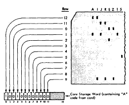 Figure 39. Normal Mode Read |
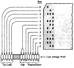 Figure 40. Load Mode Read |
An initial feed cycle results when the 1442 start key is pressed; this feeds the first card into position at the read station (sense station -- 1442 Model 5). The initial feed cycle places the 1442 in a ready condition, which is necessary before reading or punching may begin.
A constant-speed drive moves the cards through the serial path during a feed cycle. A feed cycle is initiated by a control command with modifier bits designating feed cycle, start read, or start punch. The feed cycle does three things:
An incremental drive moves the card through the punch station for punching.
When the hopper is emptied, the operator can either reload the hopper and continue operations or he can initiate a last-card sequence.
A control (start read) command initiates card reading. This command causes columns 1-80 of the card to be read in one continuous motion of the card. Each column of data is read, checked, and placed in a buffer register. A read response interrupt is given for each column read. Checking is accomplished automatically by reading each column twice and comparing the results bit by bit. This read-check-interrupt process continues until all 80 columns have been read. The last card indicator in the DSW is tumed on if the card read is the last card in the deck.
A control (start punch) command initiates card punching. As each column passes the punch station a punch response interrupt is given.
Automatic checking is accomplished by comparing the punch check echo data with the single-character punch buffer, which contains the character from the CPU. Each column punched is checked at the same time that the punch response interrupt is given for the data of the next column to be punched.
The card motion and punching process continues until the punch data word contains a one in the 12-bit position (punch data is in bits 0-11). When this end-punch bit is detected, that column is punched and the card is moved to the next column. An operation complete interrupt is given. No more punch response interrupts are given. No further punching can take place on the card.
Failure to have an end-punch bit 12 results in more than 80 columns being punched. No indication of this programming error is presented in the DSW.
A feed cycle is necessary to eject a punched card to the stacker and can be initiated by either of the three control commands: feed cycle, start read, or start punch.
A control command specifying start punch results in a feed cycle if it has not been preceded by a control command specifying feed cycle or start read.
Program load can be initiated by pressing the program load key on the 1130 console after a system reset and the "run in" cycle of a load card. This load mode causes the load-card data to be placed in 80 consecutive storage positions beginning at 00000, then causes the CPU to go to position 00000 for its next instruction.
The last-card indicator is turned on in the 1442 DSW when the last card passes the read station. The program determines when to enter the last-card sequence by testing the indicator.
When the start key is pressed without cards in the hopper, the 1442 is placed in the ready condition and allows two more feed cycles to process the last card.
The 1442 operates under direct program control of the CPU.
The card read punch is addressed by the 5-bit device code, 00010.
Read (010)
This command causes a card column image to be entered from the card reader into the core storage location specified by the address.
Write (001)
This command causes the data in the core storage locatior specified by the address of the IOCC to be punched as a column of the card.
Control (100)
This command causes the 1442 to perform the function specified by the modifier.
Modifier bits that have significance are:
| Bit 14 | Feed Cycle -- causes all cards in the feed path to advance one station. Cards pass through the read and punch stations without being processed. |
| Bit 13 | Start Read -- causes the card to move through the read station. As each column is read and checked, the card read punch initiates a read column response interrupt. |
| Bit 15 | Start Punch -- starts the punching operation and initiates a punch response interrupt. If a card is not at the punch station, a card will feed past the read station without being read. |
| Bit 8 | Stacker Select — (model 6 or 7 only) causes the card leaving the punch area to enter the alternate stacker. This control applies only to the next card leaving the punch station after this command has been issued. Selection of the desired card will not occur if the stacker select command is given while the card is still being processed at the read station. |
Modifier bits 13, 14, and 15 of this control command should not be used in combination with each other.
Sense Device (111)
This command directs the 1442 to place its device status word (Figure 41) into the ACC. Modifier bit 15 on resets responses for level 0; modifier bit 14 on resets responses for level 4.
The three interrupts associated with the 1442 are divided into two groups. The sense interrupt (011) command causes the active ILSW to be loaded into the ACC.
Figure 41. 1442 Device Status Word
Level 0 Interrupt Indicator
Read Response (Intenupt): This indicates an interrupt which signals that a column of data is ready to be entered into core storage. This interrupt request must be serviced within 800 us. for the 1442 model 6 and 700 us. for the 1442 model 7. Time from the start read to the first read column request interrupt is 28.4 ms for the model 6 and 23.8 ms for the model 7.
Punch Response (Interrupt): This indicates an interrupt which signals that a column of data must be transferred from the CPU within 300 us. Time from the start punch command to the first punch column response interrupt varies from 1.22 ms to 12.5 ms on the model 6 and 1.56 ms to 6.25 ms on the model 5 and 7.
Level 4 Interrupt Indicator
Operation Complete (Interrupt): This indicates an interrupt which occurs after a card has been processed. For reading, it indicates that column 80 of the card has passed the read station. This interrupt occurs 20.6 ms after column 80 for the model 6 and 15.4 ms after column 80 for the model 7.
For punching, this interrupt occurs after the last column to be punched has been punched and checked and the punch drive has stopped. This occurs 12.5 ms after the terminating end-punch has been detected for the model 6 and 6.25 ms after the terminating end-punch for the model 5 and 7.
The operation complete interrupt is forced if a hopper check, feed check, transport error, or feed clutch error occurs while the 1442 is busy. This interrupt is also forced by a read registration check or punch check. No subsequent reading or punching can be done in the card that caused the error. In most cases, intervention by the operator is necessary to clear the error condition before card processing may resume.
There is no time limit on the request for service of the operation complete interrupt. However, to maintain rated speed, the model 5 and 7 must be serviced within 25 ms; the model 6 must be serviced within 35 ms if reading and 25 ms if punching.
Non-Interrupt Indicators
Not Ready: This indicator shows that the 1442 is either busy or not ready. When the 1442 is not ready, manual intervention is required. The following conditions must be met to place the 1442 in a ready condition.
Busy: This indicator shows that a command cannot be started because an operation is already in progress.
Last Card: This indicator shows that column 80 of the last card has passed the read station and the hopper is empty. This indicator will be on when the operation complete interrupt occurs.
Error Check: Indicates that any of several error conditions exist on the 1442. Error conditions such as card feed failure are indicated by lamps on the 1442 console.
Programming Note: The error indicator does not turn on until after the operation complete interrupt is given. An exception to this is an XIO start punch operation requiring an automatic feed cycle. If another operation is initiated before the error indicator is turned on, the error forces an operation complete interrupt although no reading or writing has taken place. A start punch requiring an automatic feed cycle is treated as two operations: (1) feed cycle, and (2) punch operation.
This meter will run when both of the following conditions are present:
The meter will run simultaneously with the 1131 meter until either a program controlled stop or manual nonprocess runout is performed on the machine.
The IBM 2501 Card Reader (Figure 42), Model A1 and Model A2, provides card input for the IBM 1130 Computing System. Card reading is under direct program control.
The IBM 2501 model A1 reads cards at a maximum rate of 600 cards per minute (cpm); the model A2 reads at a maximum rate of 1000 cpm.
Cards are read serially -- that is, column by column -- beginning with column 1. Each column is read twice and the two readings are compared to check reading accuracy. Thus, off-punched and mispositioned cards are detected.
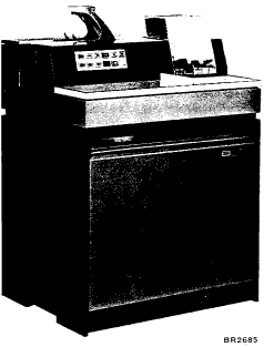
Figure 42. IBM 2501 Card Reader
The 2501 reads punched cards in card image only. Any code translation required must be done by the stored program in the CPU. As shown in Figure 39, the twelve rows (12-9) in a card column correspond to the 0-11 bits, respectively, of a core storage word.
A special load mode is initiated by pressing the program load key on the 1130 console. In the load mode, data is split as it enters core storage to form the load program. Refer to Figure 40.
After the initial feed cycle (run in), card reading may begin. Card feeding is initiated by an initiate read command. This command causes the card to begin moving. If the data is to be ignored (as in card feeding), the word count must be zero.
Card movement is as follows:
When the hopper is emptied, the 2501 leaves the ready condition. The operator may reload the hopper and press the start key to continue processing or the operator may press the start key without reloading the hopper to initiate the last card sequence.
Program load may be initiated by pressing the program load key on the 1131 console. This causes the load card data to be loaded into the first 80 core storage locations. After the card has been loaded the instruction address register is reset to 00000 and the CPU goes to this address for its next instruction.
An initiate read (110) command causes the card to be read in one continuous motion. The number of columns actually transferred to core storage depends upon the word count in the first word of the data table.
The data is read into a buffer register where it is checked. Then a cycle steal request is given for each column to be transferred. The checking is accomplished by reading the data a second time and comparing it to the data previously read into the buffer. After the last column (column 80) has been read, an operation complete interrupt is requested.
When the hopper becomes empty during a feed cycle, the 2501 is taken out of the ready status. Intervention by the operator is required to continue processing cards. The operator may reload the hopper and press the 2501 start key to continue processing or the operator may initiate the last card sequence by pressing the 2501 start key with the hopper empty.
The last card sequence places the 2501 in the ready condition for one more feed cycle and turns on the last card indicator. An operation complete interrupt is given at this time. The last card indicator remains on until a sense device command (111) is issued with bit 15 on.
The IBM 2501 Card Reader operates under the control of the stored program in the CPU.
The 2501 is addressed by the five-bit device code 01001. The address portion of the IOCC specifies the location in core storage of the data table. The first word of the data table designates the number of words to be read. This word is called the word count. The word count is located in bit positions 9 through 15 and should never exceed 80 (50 hexadecimal). If the word count exceeds 80, information in succeeding core locations is destroyed.
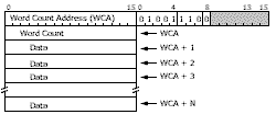
This code provides the ability to start a read operation, which subsequently makes data transfers to core storage via a data channel by means of cycle stealing.
This command sets the accumulator with the device status word (DSW) of the 2501. The DSW bits 3 and 4 (last card and operation complete) are reset if bit 15 is on when this command is executed.
Refer to Figure 43.
Not Ready or Busy: This indicates that the 2501 is not in a ready condition, or that it has received an instruction and is in the process of executing it.
Busy: This indicates that a card read is in progress and therefore another read card cannot be initiated, This indicator turns off when the operation complete interrupt occurs.
Operation Complete (Interrupt): This is the only interrupt associated with the 2501. This interrupt occurs after column 80 has passed the read station and feed checking has been completed. The operation complete interrupt is independent of the word count and terminates further cycle steal requests. The number of characters actually transferred to the CPU depends upon the word count. The 2501 is assigned to interrupt level 4. Bit 3 in ILSW 4 is turned on if the 2501 caused the interrupt. The sense interrupt (011) command causes ILSW 4 to be loaded into the accumulator if level 4 is being serviced.
Last Card: This indicates that the last card has been fed from the hopper, and the operator initiated a last-card sequence. The indicator may be turned off by a sense device command with reset (bit 15) on.
Error Check: This indicates a feed check or a read check.
There are two basic timing considerations of importance to the user of a 2501 Card Reader attached to an IBM 1130 Computing System:
The 1131 is capable of performing operations (such as reading, processing, and punching) simultaneously. After an operation is initiated, the CPU is busy for only 288 microseconds. The remainder of the card read cycle is available for other use.
Figure 43. 2501 Device Status Word
The 2501 model A1 has a 100-ms card feed cycle; the model A2 has a 60-ms card feed cycle. To maintain the rated speed, an initiate read command must occur every 100 ms for the model A1 and every 60 ms for the model A2. A basic timing consideration of importance to the user of the 2501 Card Reader is the time between the feed check signal and the feed cycle decision point. This timing is shown in Figure 44. In order to maintain rated throughput, the read instruction must be received with 18.3 ms (A1) and 3.0 ms (A2) following an interrupt (feed check signal).
If an initiate read command misses the feed cycle decision point, the card reader waits until the feed cycle decision point of the next cycle before starting to execute the command. The result in this case is the throughput is about one half of the maximum.
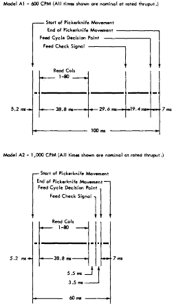
Figure 44. 2501 Timing Schematic
This meter runs when both of the following conditions are present:
The meter will continue to run simultaneously with the 1131 meter until either a last card routine is initiated by program control or a manual nonprocess runout is performed.
But wait, there's MORE...